Nuclear medicine physics is a branch of medical physics concerned with the use of radioactive materials, known as radionuclides, mainly for imaging, but also for functional measurement and therapy. Nuclear medicine imaging differs significantly from radiology, in that the radionuclides are arranged to be inside the patient, either by injection or ingestion as radiopharmaceuticals, and measured from the outside (rather than passing x-rays through the patient). This creates a number of complications, not least because the radiation cannot simply be ‘turned off’ once we are done. But it also has some very important advantages. By attaching radionuclides to biological active molecules, and then using the radiation to monitor the take up and accumulation of those molecules in different organs, we are able to perform functional imaging, giving us much more information than can be gleaned from the structural imaging offered by x-ray or CT. Similarly, for therapy, targeted take up of the radionuclide can be used to direct a radiation dose to the organ we wish to treat.
This section of the module will closely follow the required reading:
Simon Cherry, Physics in Nuclear Medicine, 4th edition.
This is available in hard copy in the library or to view online as an e-book: https://librarysearch.kent.ac.uk/client/en_GB/kent/search/detailnonmodal/ent:$002f$002fSD_ILS$002f0$002fSD_ILS:1472406/ada
Please follow along with the reading, using the chapter references given below, as the notes and the lecture slides do not contain as much detail. These notes are not a substitute for the required reading.
An atom consists of a positively charged nucleus surrounded by a cloud of negatively charged electrons. Atoms are typically \(10^{-10}\) m in diameter, a distance also known as an Angstrom, Å. The nucleus contains protons and neutrons, which are collectively known as nucleons. A nucleus is typically \(10^{-14}\) m in diameter, four orders of magnitude smaller than the atom. Protons have a charge of +1e, where \(e\) is the fundamental charge, \(1.6\times10^{-19}\) C. Neutrons are uncharged. The nucleus has a positive charge of \(Ze\) where \(Z\) is the number of protons. An atom with a full set of \(Z\) electrons of charge \(-e\) is therefore exactly neutral.
You will often see masses of nuclei given in atomic mass units, \(u\), where \(1u = 1.66\times 10^{-27}\rm\,kg\), although we won’t have much need for this. More crucially, you will regularly see energies given in units of \(\rm keV\) and \(\rm MeV\), where \(1\rm\,eV\) = \(1.6\times 10^{-19}\rm\,J\). You may also see masses given in units of \(\rm MeV/c^2\), due to the relation \(E=mc^2\).
A nuclide is a specific combination of numbers of protons and neutrons. For any nuclide we write \(\rm ^A_ZX_N\) where
X is the chemical symbol for the corresponding element
Z is the atomic number
N is the number of neutrons
A = Z + N is the atomic mass number
However, since the chemical symbol allows \(Z\) to be looked up, and \(N = A -Z\), both \(Z\) and \(N\) are redundant information. So we will often instead see simpler notations such as \(^{56}\)Fe or Iron-56. Iron has an atomic number, \(Z\), of 26, and so this nucleus has \(N = 56 - 26 = 30\) neutrons.
We then have certain names for variations:
Isotopes: Nuclides with identical Z and different N
Isobars: Nuclides with identical A.
Isotones: Nuclides with identical N
Isomers: Long-lived excited states of nuclei.
For nuclear medicine, we are mostly concerned with isotopes and isomers.
We refer to a nucleus as being in a certain (energy) state. The ground state is the lowest energy state. Excited states are states of higher energy which occur usually as the result of a decay or some other form of excitation. They are usually transient, lasting for a very short period of time (around \(10^{-12}\) s) before relaxing to the ground state. Of particular interest are metastable states. These are excited states which are stable for a comparatively long period of time (up to hours or days). They occur due to complex quantum mechanical rules which make their decay to the ground state unlikely, but we don’t need to concern ourselves with that, other than to know they exist, and as we will see later, turn out to be very important in nuclear medicine.
Required reading: Cherry 2a,d (c and c are additional background only)
While there are only 118 different elements (different values of atomic number, Z) there are over 3000 nuclides (with different values of N and/or Z) that have been experimentally observed, with around 330 occurring naturally. Of these around 250 are stable, in the sense that they do not decay over timescales comparable to the age of the universe. The nuclides found naturally correspond to only around 90 elements. That is to say that the list of stable nuclides includes isotopes of many elements (same number of protons but different number of neutrons). Smalls stable nuclei typically have \(N \approx Z\), while larger stable have \(N\) slightly larger than \(Z\), i.e. slightly more neutrons that protons, up to around \(N\approx 1.4Z\) for the largest nuclei, as shown in
In nuclear medicine, we are concerned with unstable nuclei which decay over time periods ranging from fractions of a second to millions of years. These are called radionuclies. There are many possible decay types. Alpha-decay (emission of a helium nucleus, 2 protons and 2 neutrons) and fusion (splitting of a nucleus into two or more pieces) are important for other applications (such as nuclear power), but not relevant for nuclear medicine. We are most interested in the following:
Beta minus decay (\(\beta^-\) decay) is the emission of an electron from the nucleus (and also an anti-neutrino, which does not concern us). This also involves the conversion of a neutron into a proton: \[n \rightarrow p + e^- + \bar{\nu},\]
thus changing Z but not A. For example:
\[{}^{131}_{53}\text{I} \rightarrow {}^{131}_{54}\text{Xe} + e^- +\bar{\nu}\]
\(\beta^-\) decay decay is not useful for imaging as the electrons are absorbed typically within a few millimetres in tissue, delivering an unwanted dose to the tissue and not reaching any external detector. However, some radionuclide therapies involve \(\beta^-\) decay. The kinetic energy carried by the electron varies randomly, up to some maximum, as the energy released from the decay is shared with the anti-neutrino.
Beta plus decay (\(\beta^+\) decay) is the emission of a positron (and a neutrino). A positron is an anti-electron; it has the same mass as an electron, but it positively charged. We have conversion of a proton into a neutron and so a change in the element. \[p \rightarrow n + e^+ + \nu.\]
For example:
\[{}^{18}_{9}\text{F} \rightarrow {}^{18}_{8}\text{O} + e^+ + \nu\]
When the emitted positron encounters an electron (which happens over a very short distance in tissue, around 1 mm) they two particles will annihilate. Their mass is converted to energy, in the form of two photons, each of energy 511 keV, travelling in opposite directions. This is the decay that is detected in PET (positron emission tomography), to be discussed in more detail later. The kinetic energy carried by the positron varies randomly, up to some maximum, as the energy released from the decay is shared with the neutrino, but this energy is usually dwarfed by the energy release at annihilation.
Electron capture is, in a sense, the opposite of \(\beta^+\) decay. An electron from the atom is absorbed into the nucleus, converting a proton into a neutron and neutrino. As with \(\beta\) decay, this changes the element (Z), but not A.
\[\rm p + e^- \rightarrow n + \nu\]
For example:
\[{}^{125}_{53}\text{I} + \mathrm{e^-} \rightarrow {}^{125}_{52}\text{Te} + \nu\]
Electron capture leaves a hole in the atomic orbitals for an electron. This leads to a re-arrangement of the other electrons in the atomic shells, leading to emission of a series of x-rays or Auger electrons (electrons which are ejected from the atom after absorbing energy). Auger electrons are not generally dangerous as they are low energy and only travel a few nm (the exception being if the radionuclide becomes part of the cell’s DNA).
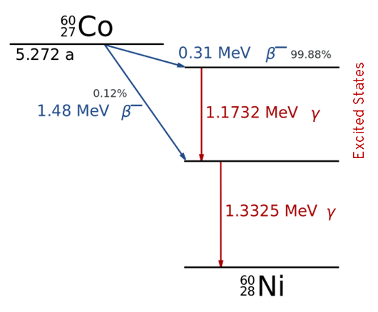
Gamma decay (\(\gamma\) decay) is the emission of a photon (a quantum of electromagnetic energy). Gamma decay occurs as the nucleus relaxes from an excited or metastable state, and is the second stage of an initial decay, such as a Beta decay or electron capture, which tend to leave the nucleus in an excited state. We can write the combined decays as, for example (\(\beta^-\), \(\gamma)\), or (EC, \(\gamma\)). The relaxation may be directly to the ground state, or via other excited states, with the latter resulting in the emission of multiple photons, one for each relaxation. The energy of each photon is fixed by the energy difference between the states.
An example energy level diagram for the decay of Co-60 by (\(\beta^-\), \(\gamma\)) decay is shown below:

Required reading: Cherry 3a,c,d,e,f,g,j (other parts of section 3 for interest).
Regardless of the type of decay, the occurrence is stochastic - we cannot determine exactly when a decay will occur, only define the probability of it occurring within a certain time period. This is given by the decay constant, \(\lambda\). As each individual nucleus has its own independent probability of decaying, the number of decays in unit time is given by \(N\lambda\), where \(N\) is the number of nuclei. The decay rate, i.e. the rate of change in the number of un-decayed nuclei, is therefore given by
\[\frac{dN}{dt} = -\lambda N.\]
The negative shows us that the number of non-decayed nuclei decreases with time.
The solution to this equation, obtained simply by separation of variables, is \[N(t) = N_0 \exp{(-\lambda t)},\]
which shows us that the number of un-decayed nuclei drops exponentially.
We further define:
The activity, A as the number of decays in a sample per unit time, \(A = \lambda N\). We define 1 Bq (Becquerel) as 1 decay per second.
The half life, \(t_{1/1}\), as the time for half of the sample to decay
The specific activity, as the number of decays per unit time per amount of sample (e.g. measured by mass or number of nuclei).
Since the activity depends on the number of nuclei, we also have \[A(t) = A_0 \exp{(-\lambda t)},\] where \(A_0\) is the initial activity.
The \(\exp{(-\lambda t)}\) term is sometimes called the decay factor. In practice, tables of decay factors as a function of time for a particular radionuclide are often used (rather than half-lives), as this makes calculations quick and straightforward: to know the activity at a certain time: simply look up the decay factor for that time and multiply by the initial activity.
The half-life is related to the decay constant, \(\lambda\), by \[t_{1/2} = \frac{\ln2}{\lambda}.\]
It is sometimes useful to know the average lifetime of a nucleus, which is simply \[\tau = \frac{1}{\lambda} = \frac{t_{1/2}}{\ln2}.\]
In practice, things are more complicated if the radionuclide can undergo different decays (known as branches). In this case we can define a decay constant for each branch, \(\lambda_1\), \(\lambda_2\), etc. The total decay constant is then the sum of the decay constants for each branch.
Required reading: Cherry 4a,b,c
When a radionuclide enters the body, we also consider the biological half-life, \(T_{1/2, \mathrm{b}}\), when determining the radiation dose that the patient will receive, or the appropriate time for imaging. The biological half life is the time taken for half of the radionuclide to be removed from the body through normal biological processes. The biological half life is often shorter than the physical half life, \(T_{1/2, \mathrm{p}}\), we have discussed above. The combined effect leads to the effective half life, given by:
\[T_{1/2, \mathrm{eff}} = \frac{ T_{1/2,\mathrm{p}} T_{1/2,\mathrm{b}} } { T_{1/2, \mathrm{p}} + T_{1/2, \mathrm{b}} }\]
When radionuclides are used in nuclear medicine, we refer to them as radiopharmaceuticals. Often, the radionuclide is chemically attached to another molecule of biological interest. In some cases this is by direct substitution, either of an isotope of the radionuclide or a chemical analogue. For example the common PET radionuclide can substitute for the hydroxyl (OH) group in glucose to form FDG (fluorodeocyglucose), which is taken up by the body in the same way as glucose. Alternatively, and more generally, larger molecules, such as proteins, can be labelled with a radionuclide that is kept far from the biological active areas of the molecule, and so does not change its function.
Only a small fraction of possible radionuclides are useful in practice for nuclear medicine imaging or therapy. There are a number of considerations as to what makes a good radionuclide, and these differ between imaging and therapy. In imaging we want to obtain information, so we care about information getting out of the patient, with as little radiation dose as possible. In therapy we want to deliver dose to the area where the nuclide is taken up (we may also want to do imaging to see where the radionuclide has gone, but that is a secondary concern).
For the ideal radionuclides, we will consider:
Decay type: For imaging, a \(\gamma\) emitter is needed. \(\gamma\) emission following electron capture is preferred over \(\beta\) decay to avoid an unwanted dose. \(\alpha\) emitters are never used. Positron emitters have a specified application in PET. For therapy, \(\beta^-\) decay is ideal, because the dose will be delivered close to where the radionuclide is taken up.
Gamma ray energy: The energy of the \(\gamma\) ray determines how likely it is to leave the body without being absorbed. Very low energy \(\gamma\) rays are also hard to build efficient detectors for, as it becomes easy to accidentally block them from reaching the active part of the detector. However, very higher energy \(\gamma\) rays are also harder to detect and impose greater constraints on the detector. In practice, energies on the order of 50 to 600 keV are practical.
Half-life: The half-life of the radionuclide is generally wanted to be in the range of hours to days. Shorter half-lives makes it impractical to store and administer, whereas longer-half lives lead to a low specific activity or unwanted long-term dose.
Specific activity: The higher the specific activity, the lower quantity of the material that has to be administered. Low quantities are desired for imaging so as not to disturb the biological system being studied.
Chemical properties: For many imaging studies, the radionuclide must be attached to a molecule which is taken up by the organ of interest. It is therefore desirable that the radionuclide is convenient to chemically attach to the required molecules, by one of the methods discussed above.
While some radionuclides occur naturally, these tend to have very long half-lives (otherwise they would have long since disappeared), or are being replenished because they are the product of another decay with a long half life. However, useful radionuclides are not obtained from natural sources. Instead they are produced artificially, in one of the following ways:
Nuclear Reactors: Some radionuclides are naturally produced as by-products of nuclear fission reactors used to generate energy. Whether this is practical depends on whether the particular radionuclide is produced in significant quantities from the fission of the Uranium-235, and also whether other isotopes of the same element are also produced (since these cannot then easily be separated by chemical means). Other radionuclides can be produced by placing materials in the reactor that will then be bombarded with neutrons, resulting in ‘activation’, i.e. creation of a radionuclide. For the exam, you do not need to know details of these production methods.
Accelerators: An accelerator can be used to accelerate charged particle, such as protons, to high speeds using an electric field. They are then allowed to smash into a target, resulting in the generation of radionuclides. A particular type of accelator, called a cylclotron, is most commonly used. The ‘cyclo’ part of the name refers to the fact that the charged particles are accelerated in a spiral, re-using the same electric field multiple time, which allows for a much more compact accelerator and higher speeds to be achieved. Magnetic fields are used to force the charges particle into a spiral path. Cyclotrons can be used are used to produce a range of radionuclides, particularly those that decay by \(\beta^+\) and electron capture (since smashing positively charged particles into the target tends to produce proton-rich radionuclides that decay in these ways). In particularly, PET radionuclides, such as are produced this way (see the PET section for more details). Since these radionuclides often have short half-lives (e.g. is 109 minutes), a network of cyclotrons is required to supply hospitals (for example there are around 20 in the UK). For the exam, you do not need to know details of these production methods.
Generators: A generator is a device which stores a parent radionuclide which decays into a daughter radionuclide, which is the radionuclide we want to use. Generators are small and can be kept at hospital sites As long as the parent radionuclide has a longer half-life, this means that less regular deliveries to the hospital are required. For the exam, you should know the basic ideas behind the Molybdenum generator, discussed below.
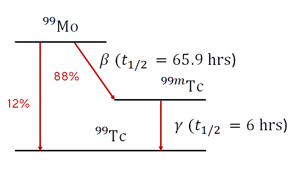
Technicium 99-m (Tc-99m) is by far the most commonly used radionuclide in nuclear medicine imaging (outside of PET) and so deserves some particular attention. It is a metastable state, i.e. an isomer, of Tc-99, which is indicated by the ‘m’. The energy level diagram for the its production from Mo-99 (Molybdenum) is shown below.
Tc-99m has the following properties:
Tc-99m decays to Tc-99 with a half life 6 hours. This is long enough to allow time for the radiopharmaceutical to be injected and taken up by the organ of interest before imaging, but short enough that the patient will no longer be radioactive within a day or so.
Tc-99m has a biological half life of, typically, less than 3 hours, and so the radiation dose to the patient is even lower than the physical half life would suggest.
The decay product, ground state Tc-99, is a radioactive \(\beta\) emitter, but with a half-life of 210,000 years and so does not present any residual radiation hazard in the small quantities involved.
Tc-99m decays primarily by emission of a single \(\gamma\) ray with an energy of 140 keV. This is comparable to the energies used in radiology, and is in the ideal range for detectability whilst minimising patient dose.
While Tc-99m cannot be stored in hospitals for long periods due to the 6 hour half-life, it can be produced on site using a Molybdenum generator, discussed in more detail below. This avoids the need for daily delivery (as is the case for most PET radionuclides, for example).
A Molybdenum generator is a small device which can be used to produce Tc-99m locally, e.g. at a hospital. The generator contains Molybdenum-99 in the form of the ion \(\rm MoO^{2-}_4\) or molybdate. This is bound to an alumina column. Mo-99 decays to Tc-99m with a half life of 66 hours. The decay product is in the form of \(\rm ^{99m}TcO^-_4\) (pertechnate) which does not bind to the column as strongly as molybdate and can be eluated (washed out) by passing saline (salt water) over the column, with an efficiency of over 80%. The same generator can be used many times, once the pertechnate has been allowed to build up again through decay of the remaining Mo-99. After about a week, remaining activity of Mo-99 is too low, and the generator is replaced.
If the Tc-99m is not eluted, it would not build up indefinitely, because the Tc-99m is also decaying. This results in a steady state (technically known as a transient equilibrium) maximum quantity of Tc-99m in the generator after about 24 hours. This makes the generator ideal for daily elution for use for the day’s nuclear medicine studies, although more regular elutions can be performed if needed.
The generator will also contain Tc-99, due to the decay of Tc-99m. This is washed out along with the Tc-99m, resulting in a lower specific activity, particularly if the generator is left for a few days. Regular elution is therefore needed to maintain a high specific activity.
The Mo-99 is made in a nuclear reactor by neutron activation of U-238. Special facilities are then required to extract the Mo-99 (For the exam, you don’t need to know the details of this). This is only performed at a handful of sites worldwide. In 2009-12, two of the reactors producing Mo-99 were temporarily shut down at the same time, resulting a major worldwide shortage of Mo-99 and hence Tc-99m
Required reading: Cherry 5 a,b (background, not all details needed); c,e,f (in detail).
For most studies using Tc-99m, the Tc-99m eluted from the generator has to be bound to a biological molecule relevant to the imaging study forming a complex. For example, for a bone scan, Tc-99m can be bound to diphosphonate. The complexes can be made up in the hospital radiopharamcy using pre-prepared kits, to which the eluted Tc-99m is added.
The gamma camera is the workhorse of nuclear medicine. Its purpose is to perform radionuclide imaging, i.e. to obtain an image showing the distribution of the radioactive tracer inside the body. This is also known as scintigraphy, and gamma camera are sometimes referred to as Anger cameras after their inventor. Gamma cameras can be used to generate both planar (i.e. 2D) scans as well as 3D tomograms, in which case this is referred to as SPECT (single photon emission computed tomography).
\(\gamma\)- rays can be detected by a combination of a scintillation crystal, a light guide and photomultiplier tubes (PMTs). A scintillator is a material that absorbs \(\gamma\)-ray radiation and emits (multiple) photons of visible light. The amount of light emitted is proportional to the energy of the \(\gamma\)-ray. The scintillators in gamma cameras are usually made from from Thallium-doped Sodium Iodide NaI(Tl). A simplified diagram of a gamma camera head is shown below:

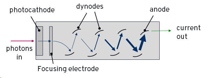
Light emitted from the scintillator is amplified in the photomultiplier tubes (PMTs). A PMT has an entrance window containing a photoemissive material which is connected to a power-supply so that it is negatively charged - i.e. it is a photocathode. It will emit an electron when struck by a photon of light. Inside the tube, the electron is accelerated towards a series of increasingly positively charged plates, called dynodes. When it strikes the first plate, the electron causes the emission of more electrons, known as secondary electrons. Each of these secondary electrons is accelerated towards the next plate, causing more emissions, and so on. The end result is a large shower of electrons arriving at the end of the tube where they strike the most charged plate, the anode, and create an electric current.
Each plate multiplies the number of electron by around a factor of 3-6, and there are usually 10 or more plates in total, meaning that the initial electron created by the single photon results in hundreds of thousand to millions of electrons striking the anode and generating a large current. In this way, the PMT is sensitive to the single photon level. A simplified diagram of a PMT is shown below:
The PMTs may be joined to the scintillator via a simple transparent window, or in some cases a plastic light guide that increases efficiency of the coupling of light into the PMTs. The PMTs do not work like pixels in a camera; there are only a few 10s of PMTs in a typical detector head, which would give very poor resolution. Instead, we rely on the fact that when a \(\gamma\)-ray is absorbed in the scintillator, it produces a cone of visible phones that will be detected by more than one PMT. By looking at the relative signal level in multiple PMTs, we can identify the location of the \(\gamma\)-ray detection in the scintillator. This is illustrated for a simplified 2D case below:
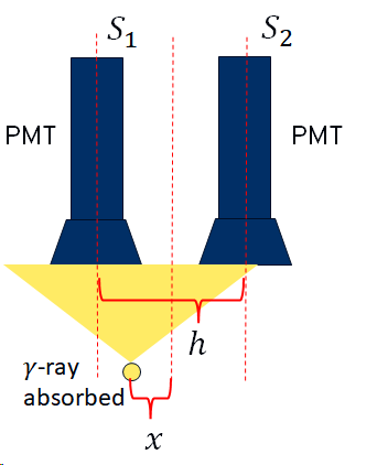
\(S_1\) and \(S_2\) are the signal levels from the two PMTs. The position of the detection relative to the mid-point between the two PMTS is then given by:
\[\frac{x}{h} = \frac{S_2 - S_1}{S_2 + S_1}\]
This assumes that the signal level is inversely linearly proportional to the distance. It turns out this isn’t quite true, and so uniformity corrections need to be applied (discussed later)
Gamma cameras must be fitted with a collimator in order to obtain useful images. A collimator is a sheet of material that is strongly absorbing of \(\gamma\)-rays, usually lead, with holes. The walls between the holes are called septa. Without a collimator, points on the patient are not imaged onto the camera, as illustrated below:
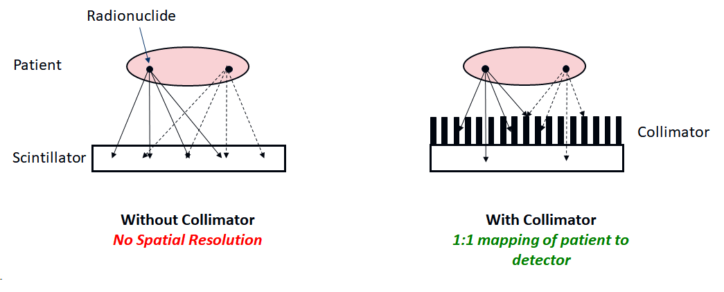
Without a collimator, a point source of radiation would simply result in a large ‘blob’ on the detector. The collimator ensures that only \(\gamma\)-rays travelling approximately perpendicular to the camera can reach the scintillator, thus restoring a mapping between distribution of radionuclide in the the patient and the camera. This is similar to the function of a lens in a camera (we cannot make a lens for \(\gamma\)-rays). Since most of the \(\gamma\)-rays will not be travelling perpendicular to the collimator, they will be absorbed by the septa, and so the efficiency of detection is very low.
The resolution of the images depends on both the intrinsic resolution of the gamma camera, and the resolution of the collimator. The combined or system resolution is given by:
\[R_{sys}^2 = R_{int}^2 + R_{coll}^2\]
and hence is always worse than both.
The intrinsic resolution is the ‘spread’ due to effects within the camera itself. For example, the finite thickness of the scintillator means that there is uncertainty over where the visible photons are originating from, and also leads to the possibility of scatter, changing the apparent source of the \(\gamma\)-ray. However, a certain degree of thickness is required for efficient detection. The intrinsic resolution is usually on the order of a few millimetres.
From geometrical considerations, the resolution of the collimator is given by:
\[R_{coll} = d\bigg(\frac{l + b}{l} \bigg)\]
where \(l\) is the length of the septa wall, \(d\) is the size of the hole and \(b\) is the distance of the patient from the collimator. This is illustrated below:
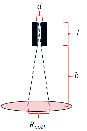
Notice that the resolution is strongly dependent on the distance of the patient from the collimator. That is why the patient is always positioned as close as possible to the camera.
If the septal walls are too thin, some \(\gamma\)-rays happen to penetrate the wall, again degrading resolution. In practice we cannot make the septal walls too thick, as this will eventually reduce the number of detected \(\gamma\)-rays to too low a level, and so there is again a trade-off between signal level (and hence scan time) and resolution. Since the probability of gamma rays penetrating the septa depends on their energy, this trade-off varies with decay energy. A gamma camera will therefore come with several sets of collimators which are exchanged depending on the radionuclide being imaged and the aims of the study. These have names such as LEHR (low-energy, high-resolution), LEAP (low-energy, all purpose), MEHR (medium-energy, high resolution) and so on. (You don’t need to know the details of these).
In addition to having collimators with parallel septa, collimators have also been designed with diverging or converging septa, or using a pinhole. (Again, you don’t need to know the details of these.)
It will often happen that \(\gamma\)-rays will scatter within the body (or the camera itself) and hence change direction. This degrades the image, as the apparent origin of the \(\gamma\)-ray is no longer the real location of the radionuclide. In general, there are large amounts of scattering when using low energy emitters such as Tc-99m, which would tend to lead to large background signal that obscures the real signal of interest.
This problem can be mitigated by exploiting the fact that at the energies used in nuclear medicine, Compton scattering dominates over elastic scattering, i.e. the \(\gamma\)-rays lose energy when they scatter. Hence, by only counting detections within an energy window around the known decay energy, scattered \(\gamma\)-ray detections can be rejected. Typically a window size of around 10% - 20% of the peak energy is used.
It is critical that the gamma camera produced images that are uniform - i.e. a uniform distribution of radionuclide must give a uniform image. This can be tested by imaging either a point source of radiation (e.g. a syringe) with the collimators removed (intrinsic uniformity) or a sheet of radioactive material with the collimators fitted (extrinsic uniformity). The images can then be used to calibrate out any non-uniformities - i.e. to generated a correction that will be applied to future images.
Required reading: Cherry Sections 13, 14A, 14B (in outline only), 14C, 14E (in outline), 15 (for background, don’t need to know details.)
To obtain 3D images, the gamma camera is sequentially positioned at different angles around the patient, collecting a gamma camera image at each location. The number of positions depends on the study, but 50-100 is typical. The camera camera can either sit at each position for some time, usually 10s of seconds, called ‘step and shoot’, or (less commonly) rotate continuously. To speed this process up, most SPECT-enabled cameras come with two heads, positioned on opposite sides of the patient, and some specialist machines come with three.
The multiple projections are then processed to generate a 3D volume or tomogram. This can be done using the same filtered-back-projection algorithms as used in CT. The concept of back-projection is that we take the first projection (which is the integral of the activity along lines perpendicular to the colliamtor) and assume that the radiation was equally distributed along the line. We then take the second projection, do the same, and then add the results to the first back-projection. If we do this for each projection, we end up with an approximation to the original distribution of radiation, as illustrated below.
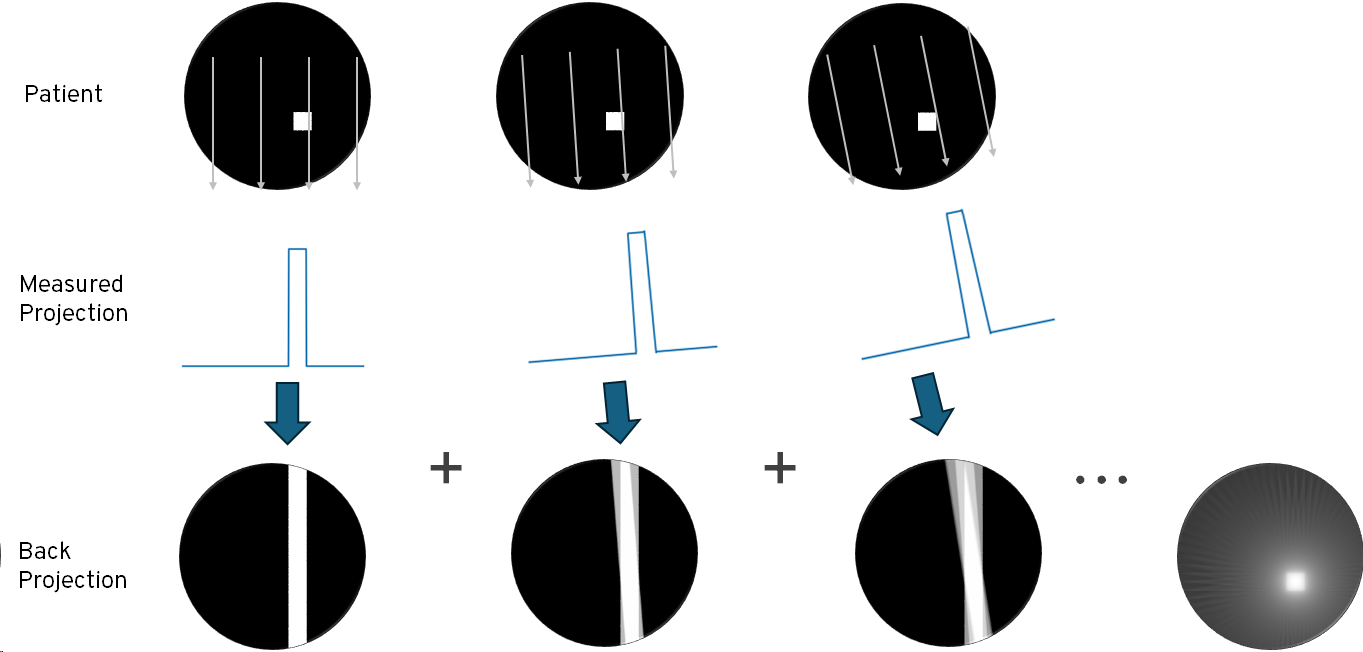
Back-projection tends to amplify low spatial frequencies, resulting in a ‘blurred’ image, and so better results are obtained by applying a high pass filter to each projection prior to back-projection. The results of applying a simple ramp filter are shown below. In practice, a more sophisticated filters that attenuate high frequencies and artefacts can be used. Artefacts can also be reduced by increasing the number of projections, at the cost of acquisition time.

For nuclear medicine in particular, better results can usually be obtained using iterative methods. The general idea is that we start with an initial guess for the distribution of the radionuclides (e.g. by taking the result of back-projection), and then we ‘forward-project’ - we simulate the expected projections seen on the gamma camera. Since these will not match, we then perturb the distribution of radiation and see if this results in a better match. If it does, then we continue to perturb in the same ‘direction’. This process continues until a stable solution is found. The details of this are quite complex and are not needed for this module.
An important difference between SPECT and CT is that, unlike CT, SPECT does not change the radiation dose that the patient receives. However, many SPECT enabled gamma cameras can also generate CT images. These are useful both to relate the SPECT images to the patient anatomy, and can also be used for attenuation correction, i.e. to adjust the SPECT tomograms to account for the fact that different parts of the body will absorb differing fraction of the \(\gamma\)-rays prior to the camera.
Required reading: Cherry 16A, 16B (in outline), 16C,D (for background only)
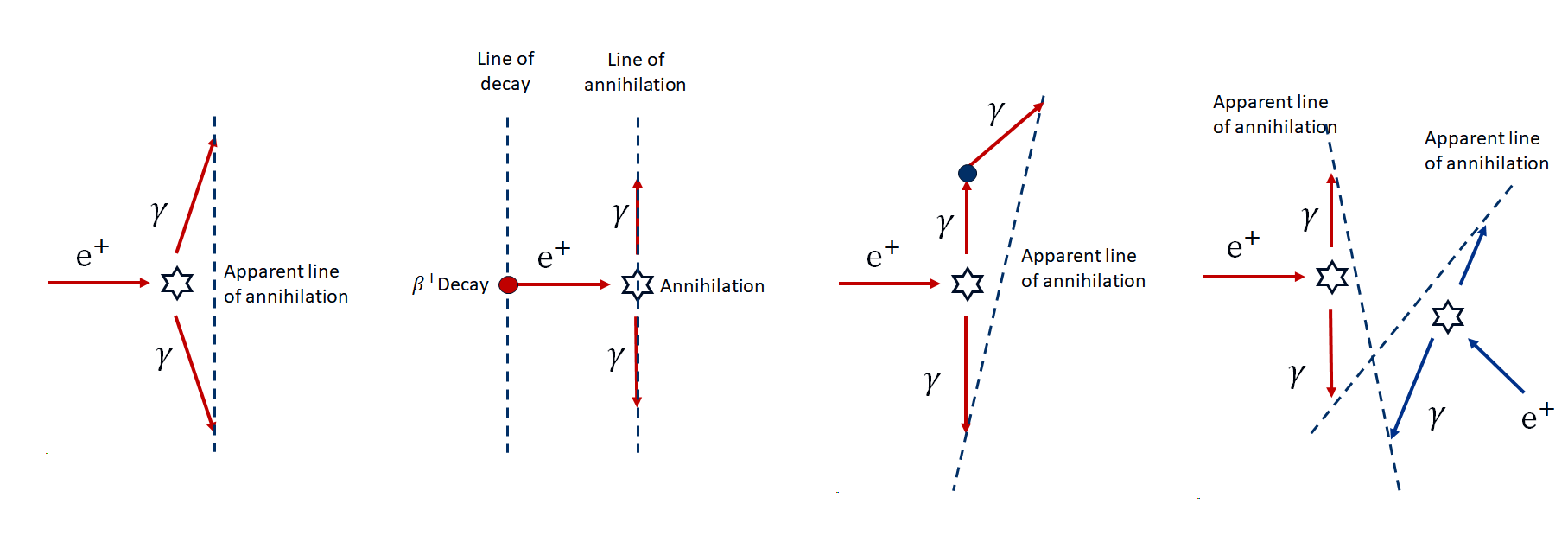
PET also provides tomographic images, but works in a fundamentally different way to SPECT. It works using positron emitters, such as Fluorine-18. As discussed previously, positrons annihilate with an electron within a short distance of emission, resulting in to \(\gamma\)-rays that must travel in opposite directions in order conserve momentum, and each carry 511 keV of energy. PET uses a ring of detectors to detect both of these photons, known as ‘co-incidence detection’. We then know that the emission was somewhere along the straight line between the two detections, as illustrated below:
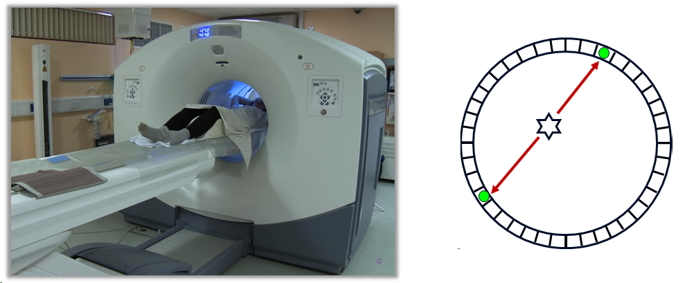
Collecting a large number of such co-incidences effectively produces projections, in a conceptually similar way to SPECT. Tomographic reconstruction can then be performed. The patient is moved through the ring of detectors on a bed, to allow some or all of the body to be imaged. Again, a CT image will often also be acquired by the same machine (PET-CT).
There are several sources of positional error in PET that effect resolution and/or increase noise over what we might expect:
Non-colinearity: As the positron will have some energy and momentum prior to annihilation, the \(\gamma\)-rays do not travel at exactly \(180^0\).
Positron travel distance: The positron will travel a short distance (up to 1 or 2 mm) before annihilation, and so we do not detect the real positron of the emission.
Scattering: Scattering of \(\gamma\)-rays will obscure the true source and hence the location of the emission. Since this is mostly Compton scattering (i.e. there is an ernergy loss), in principle these could be rejected by energy discrimination. However, the poor energy resolution of most PET detectors means that small angle scattering is hard to remove.
Random co-incidences: \(\gamma\)-rays arriving from two unrelated decays arriving at the detector ring within the co-incidence time window results in spurious detections.
These four effects are illustrated below:
The detectors in a PET camera use a similar principle to a gamma camera: a scintillator and PMTs, as shown below. Each segment of the detector would typically contain 4 PMTs and runs independently of the other segments in the ring. Positional detection using the 4 PMTs (similar to a gamma camera) gives a positioning resolution which is smaller than the size of the segment. The scintillator is chosen to optimise for 511 keV, often bismuth germanate (BSO) rather than the NaI(Tl) used in most gamma cameras.

The most common radiopharmaceutical used for PET imaging is Fluorodeoxyglucose, or FDG. This is an analogue of glucose, with one of the hydroxyl groups replaced with radioactive F-18. Glucose, and FDG, is taken up at sites of increased metabolic activity, which include sites of tumour growth, as well as in the brain. FDG is therefore often use for cancer staging and functional brain scans.
F-18, as a positron emitter, is produced in a cyclotron and has a half-life of 110 minutes. A hospital therefore either needs a cyclotron on-site, or regular (at least daily) deliveries.
A more recent development of PET is known as time-of-flight or TOF-PET. In TOF, the difference in the arrival times between the two \(\gamma\)-rays is used infer additional information about the position of the decay. If time-resolution was arbitrarily good, this would allow tomographic reconstruction directly. In practice, TOF-PET detectors have a time-resolution of around 500 ps in the best case, which serves only to localise to around 15 cm. However, this additional information can be used to help constrain the iterative reconstruction, leading to higher quality (i.e. less noisy) reconstructions.
Required reading: Cherry 18A, 18B (in outline), 18E, 18F
Radioactive iodine, in the form of I-131, is used for treatment of the thyroid.
Iodine-131 is a major product of nuclear fission of U-235 and Plutonium, and so is produced in significant quantities in both nuclear reactors and in nuclear weapons. It was one of the major hazards following Chernobyl, and from above-ground nuclear weapons tests prior to 1963. However, as fission products are difficult to recover and separate, I-131 for therapeutic use is usually produced from neutron bombardment of a Tellurium target in a nuclear reactor.
I-131 decays to Xe-131, mostly by \(\beta^-\) emission, with a half-life of 8 days. There is also a 364 keV \(\gamma\)-emission. This is not useful for the therapy, and is a radiation hazard, but it can be used for imaging to check take-up. I-131 is not used for imaging alone, I-123 is a better alternative.
The thyroid is a gland in the neck, close to the trachea and larynx. The thyroid produces the hormone thyroxine, which among other things controls the body’s metabolic rate. Unusually, the thyroxine molecule contains iodine, and so iodine in human diets is efficiently transported to the thyroid. Oral administration of I-131 therefore results in a large radiation dose to the thyroid via \(\beta\)-emission, and only a limited dose elsewhere in the body.
I-131 is used for treatment of two conditions:
Hyperthyroidism: An overactive thyroid leads to a higher metabolic rate than normal, with symptoms including rapid/irregular heartbeat, hunger, weight loss, etc. It is often caused by Graves’ disease, an immune system disorder. Treatment with (typically) 300 MBq of I-131 results in a permanent reduction in the rate of thyroxine produced. The consequence may be an under-active thyroid, but this is easily managed by taking oral thyroxine.
Thyroid Cancer: Following surgical removal of the thyroid, remaining thyroid tissue can be destroyed using a larger dose, typically 2 GBq, of I-131.
I-131 therapy, particularly the larger dose used for cancer treatment, represents a significant radiation protection challenge. The body clears the I-131 reasonably quickly, with a biological half-life of around a day, but it may still take several days for the patient to have an activity low enough for them to leave an isolation room (usually set at 800 MBq in the UK).
The retained activity in the patient can be estimated using a dosemeter at regular intervals. This doesn’t measure activity directly, but since the activity just after ingestion is known, a reading at this point allows future readings to be converted to an estimate of the activity. This relies on the measurements being made in a consistent way (e.g. with the dosemeter placed 1 m from the patient), and is subject to many uncertainties, including the redistribution of the I-131 around the body.
The isolation room is specially prepared for the patient, including covering items and surfaces in disposable plastic sheeting, to prevent contamination. It is important to note that as the physical half life of I-131 is 8 days, any contaminated items will remain radioactive for longer than the patient. Once the patient is released, the plastic sheeting can be moved to a decay store, where it is kept until the activity is low enough for it to be disposed of in the normal waste stream. During the patient’s stay, contact with staff and visitors is kept to a minimum, while always maximising the distance to minimise the dose they will receive.