Physics and Astronomy, University of Kent
Geometrical optics is a much simpler way to treat light than wave optics, but it is sufficient for many applications. We treat light as ‘rays’ which, in a uniform medium, travel in straight lines. At interfaces these rays can be reflected or refracted, resulting in a change of direction that can be derived from Fermat’s Principle.
We must always remember that geometrical optics is not physical, in reality there is no such thing as a ray of light. So we mustn’t take geometrical optics too far, if we seem to predict something that is at odds with the wave theory of light then we know that it is the wave theory of light that is correct. Geometrical optics, for example, has nothing to say about diffraction. Nevertheless, it is a very useful model; a great deal of industrial optical design is performed using ray tracing software such as Zemax and Code V, which for the most part use geometrical optics.
Fermat’s principle is simple to state, but allows us to calculate and derive a number of important rules in geometrical optics, including the laws of reflection and refraction.
Fermat’s principle states that the path taken by light in travelling from one point to another is such that the travel time is minimum.
In uniform media, this is equivalent to saying that light travels in straight lines. When light moves between media with different refractive indices, things become more interesting.
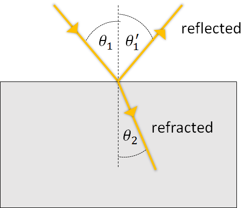
When a ray of light hits the boundary between two transparent media with different refractive indices, the beam is partially reflected and partially refracted. The angle of the reflected beam is equal to the angle of the incident beam, when both are measured with respect to the normal of the interface.

\[\theta_1' = \theta_1\]
The portion of the beam which enters the second medium experiences a change in direction, known as refraction (providing the ray is not perpendicular to the boundary). The relationship between the angle of incidence, \(\theta_1\), and the angle of refraction, \(\theta_2\) (i.e. the angles before and after passing the boundary) is given by Snell’s Law.
\[n_1 \sin\theta_1 = n_2 \sin \theta_2 \label{snell}\] where \(n_1\) is the refractive index of the first medium, \(n_2\) is the refractive index of the second medium, \(\theta_1\) is the angle of incidence and \(\theta_2\) is the angle of refraction. The angles are measured with respect to the surface normal, an imaginary line perpendicular to the boundary.
It is useful to remember that as light enters a medium with a higher refractive index (e.g. from air to glass) it bends towards the normal. As it goes to a lower refractive index, it bends away from the normal.
For normally incident light, \(\theta_1 = 0\), the fraction of the intensity which is reflected, rather than refracted, is: \[\frac{I_{reflected}}{I_{incident}} = \bigg( \frac{n_1 - n_2}{n_1 + n_2} \bigg)^2\]
For other angles of incidence, the fraction reflected is dependent on several other factors, beyond the scope of this course. For light normally incident on an air/glass interface, the reflected intensity is around 4%. This means that, in an optical system, every (untreated) glass surface which light hits results in a 4% loss. In practice, special coatings can be applied to reduce the reflected intensity to a fraction of one percent. Or, we may want to make a mirror, in which case we apply a coating or backing which increases the reflected intensity to 90% or more (depending on how much you want to spend on your mirror).
If we look at Snell’s Law we might notice that, when going from a higher to lower refractive index, there is going to be some range of incident angles for which the angle of refraction becomes larger than \(90^o\). What happens then? At this point there is no refraction, and all the light is reflected back into the denser medium. This is called total internal reflection. This has many important applications, in fact it is the geometrical optics explanation for how fibre optics transmit light without losses (although a full understanding of fibre optics requires an analysis using a wave model of light).
The angle of incidence for which the angle of refraction is \(90^o\) is called the critical angle. For angles of incidence greater than this, there is no refracted ray. We can find this critical angle, \(\theta_c\) by setting the angle of refraction equal to \(90^o\) in Snell’s Law. \[\sin \theta_c = \frac{n_2}{n_1} \sin 90^o = \frac{n_2}{n_1}\]
and so \[\theta_c = \arcsin \frac{n_2}{n_1}\]
Note that total internal reflection can only happen inside the medium with higher refractive index.
In Chapter 1 we saw that the refractive index of materials has a wavelength dependence. Now we can see from Snell’s Law that the angle of refraction will then depend on wavelength. This explains why we see a spectrum from a prism (or a rainbow in the sky!).
In the paraxial approximation we assume that all light rays travel at a small angle relative to the optical axis. The optical axis is the line running perpendicular to elements such as lenses and mirrors. Among other simplifications, this allows us to make the small angle approximation, \(\sin \theta \approx \theta\). We will see example of this in what follows.
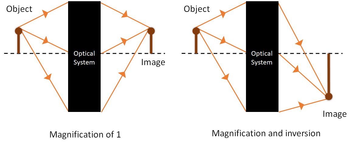
In the following sections and Chapter 3 we will be studying optical elements used to create images, so it is important to understand what we mean by an image. If we have an object, it will scatter (or emit) light in all directions. In order to form an image, we need to collect rays coming from a particular point on the image, and focus them to a point. Rays from other points on the object must also be focused to points on the image plane, with their geometrical relationship maintained. This allows for magnification and inversion, as illustrated in Figure 2.
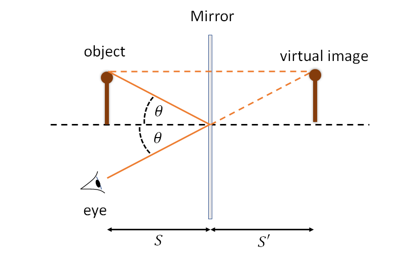
When we look at an object in a mirror, we see a virtual image of the object behind the mirror. This is illustrated in Figure 3, where a bundle of rays from an object is reflected from a plane mirror. For someone looking at the object in the mirror, the rays appear to converge from a point behind the mirror. This is the location of the virtual image, and we can find this point by tracing the rays back, as shown.
The virtual image is the same distance from the mirror as the object, it is the same way up (i.e. not inverted), and it is the same size. However, it is depth-inverted - a right hand viewed in a mirror looks like a left hand. Our brains tend to interpret this as a horizontal flip (because depth inversion is quite a tricky thing to visualise), but this is an illusion. After all, why would it flip on one-axis but not the other?
A spherical mirror is a mirror shaped like part of the surface of a sphere. We define the radius of curvature , \(R\) as the radius of the sphere which the surface is part of. If we have collimated rays striking a spherical mirror on-axis, they will be focused to a point P, as shown in Figure 4. The distance from the mirror to this point is the focal length of the mirror, \(f\). It is given by \[f = \frac{R}{2}\]
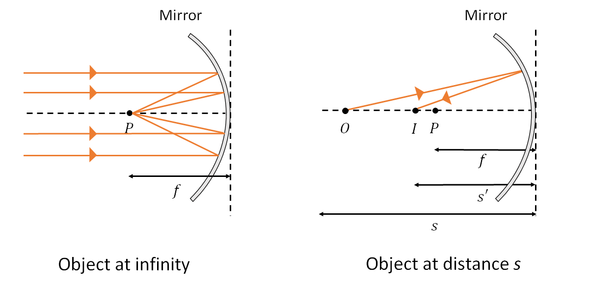
So, if we have an object at infinity, creating collimated rays, then an image will be formed at the focal length, \(f\). If we have an object at a finite distance, \(s\), then the image will instead be formed at \(s'\). These distances are related by the mirror equation:
\[\frac{1}{s} + \frac{1}{s'} = \frac{1}{f}\]
The image is inverted and has linear or lateral magnification given by: \[M = -\frac{s'}{s}\] The minus sign is to remind us that the image is inverted. If the object is placed between the mirror and the focal length, \(s < f\), then there is no real image. Reflected rays appear to emerge from a virtual image a distance \(s'\) behind the mirror.
Note that a spherical lens only forms an image correctly under the paraxial approximation.
To relate the positions of the image and the object to the radius of curvature, and ultimately the focal length of the mirror, we start with the diagram shown in Figure 5. We have an object at \(O\) and and image at \(I\). The point is \(C\) is the centre of the ‘circle’, i.e. all points on the mirror are a distance \(R\) from this point. A ray from the object hits the mirror at point \(A\), a height \(h\) above the optical axis. We label the angles \(\alpha\), \(\beta\) and \(\gamma\) as shown, and we also identify the two angles \(\theta\) which are equal as per the law of reflection.
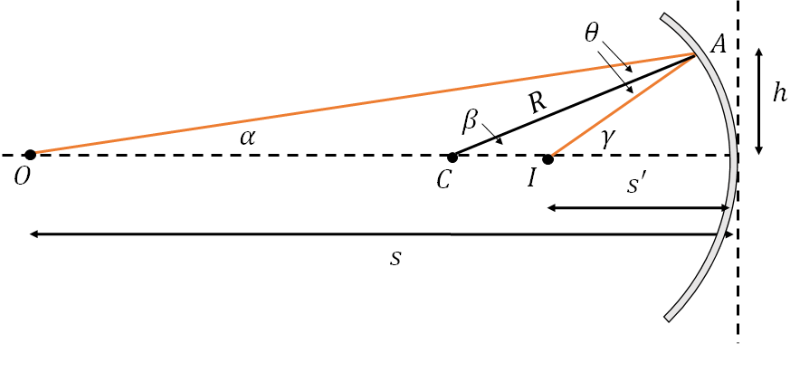
From the triangle OAC we have \(\alpha + \theta + (180^0 - \beta) = 180^o\). From the triangle CAI we have \(\beta + \theta + (180 - \gamma) = 180^o\). Eliminating \(\theta\) gives: \[2 \beta = \alpha + \gamma \label{beta_eqn}\]
From the paraxial approximation, \(\alpha = h/s\) and \(\beta = h/R\) and \(\gamma = h/s'\). Substituting into Equation [beta_eqn] gives: \[\begin{aligned} \frac{2h}{R} &= \frac{h}{s} + \frac{h}{s'} \\ \frac{2}{R} &= \frac{1}{s} + \frac{1}{s'} \\ \end{aligned}\]
To show that \(f = R/2\) we consider what happens as the object position \(s\) tends to infinity, which means that, by definition, the image will now be at the focal point, i.e. \[\begin{aligned} \frac{2}{R} &= \frac{1}{s'} \\ \frac{2}{R} &= \frac{1}{f} \\ f &= \frac{R}{2} \end{aligned}\] and so: \[\frac{1}{f} = \frac{1}{s} + \frac{1}{s'} \\\]
A lens is piece of glass with one or both of its surfaces curved in such a way as to cause light rays to converge or diverge due to refraction. In what is follows, we use the thin lens approximation, which ignores the thickness of the lens. In which case, the locations of the object (\(s\)) and image (\(s'\)) for a lens are linked to the focal length of the lens, \(f\), by the lens equation:
\[\frac{1}{f} = \frac{1}{s} + \frac{1}{s'}\]
If we have a lens of focal length \(f\), and we place an object a distance of \(s\) one side of the lens, we obtain an image a distance \(s'\) the other side of the lens.
Note that \(s\) and \(s'\) are both measured from the lens outwards (i.e. \(s\) is measured from right to left and \(s'\) is measured from left to right.) An object to the left of the lens has a positive \(s\) and an image to the right of the lens has a positive \(s'\). This is called the Gaussian co-ordinate system. An alternative system, the Cartesian co-ordinates system, measures everything from left to right which can actually be more useful when dealing with some kinds of systems and is used in raytracing software. In this case, the lens equation would have a minus sign before the \(1/s'\) term.
The focal length \(f\) is fixed for a given lens, it depends on the curvature of its surface according to the lens makers’ equation: \[\frac{1}{f} =(n-1)\bigg(\frac{1}{r_1}-\frac{1}{r_2} \bigg)\]
where \(r_1\) is the radius of curvature of the first surface of the lens, \(r_2\) is the radius of curvature of the second surface, and \(n\) is the refractive index of the lens material.
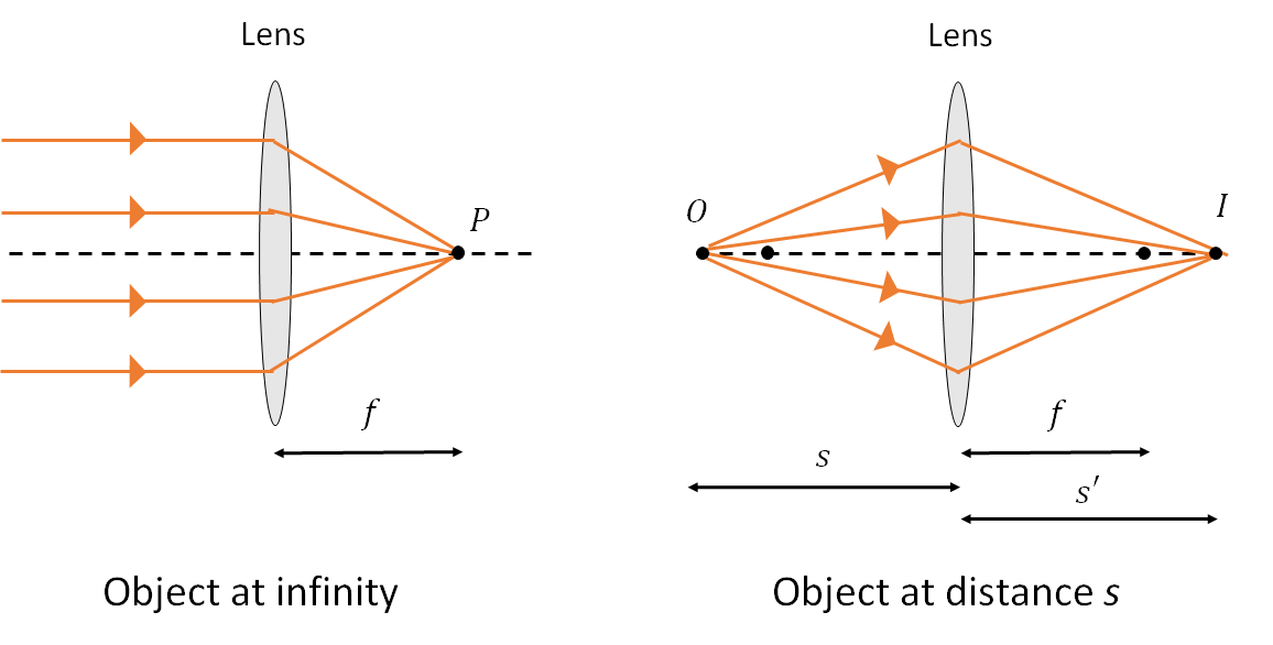
A real image is obtained for \(s > f\). Otherwise there will be no real image, and \(s'\) is negative, with rays appearing to diverge from a virtual image at \(s'\) (i.e. on the left side of the lens, as drawn).
The linear magnification, the ratio of the size of the image to the size of the object, \(M\), is given by \[M = -\frac{s'}{s}\]
The minus sign tells us that the image is inverted.