Physics and Astronomy, University of Kent
A full description of the propagation of light is a complex endeavour. Light is an electromagnetic wave, and so understanding it rigorously involves solving Maxwell’s Equations (which you will do in later Stages). Luckily, for many practical purposes there are large set of simplifications which can be made, allowing us to predict the behaviour of light accurately enough to be useful. In these lectures, after a brief introduction to the wave nature of light, we will introduce the approximation known as ‘geometrical optics’, treating light as ‘rays’. This will allow us to model simple ideas such as reflection and refraction Even geometrical optics can become fiendishly complex, and so we will largely restrict ourselves to a further approximation known as the paraxial approximation, which means only dealing with light rays which move on, or close to, the optical axis. Despite the apparent severity of these approximations, our picture will be useful enough to allow us to understand the operation of several important optical devices, including telescopes and microscopes.
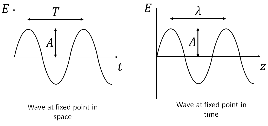
Light is a wave in the electromagnetic field, and so this module is linked to the waves section of ‘Mechanics and Waves‘. Like any wave, a light wave can be described in terms of its amplitude (\(A\)), frequency (\(f\)), wavelength (\(\lambda\)), period (\(T\)), and phase (\(\phi\)). We also define the wavenumber, \(k = 2\pi/ \lambda\) and the angular frequency \(\omega = 2\pi f\). Then we can write an expression for the magnitude of the electric field as a function of position (\(z\)) and time (\(t\)): \[E = A sin(kz - \omega t + \phi)\] where \(\phi\) is some initial phase. We could write something similar for \(B\), as it turns out for a travelling electromagnetic wave \(E\) and \(B\) vary in the same way (they have the same frequency/wavelength but the oscillations are perpendicular to each other, at least in the idealised case). This is beyond the scope of this module, but you will learn more about it in Stages 2 and 3.
From the equation it is clear that the field varies in both time and space, so when we draw a wave we need to be clear what we are drawing - either the spatial wave at a fixed point in time (\(t\)), or the temporal wave at a fixed point in space (\(z\)) (see Figure 1).

The argument of the \(\sin\) function is called the phase. This tells us the point in the wave cycle we have reached at particular point in space and time. This is expressed as an angle, with a phase of \(2\pi\) equivalent to a complete cycle of the wave. After a phase of \(2\pi\) we are back where we started, so for example a phase of \(5\pi/2\) is the same as a phase of \(\pi/2\).
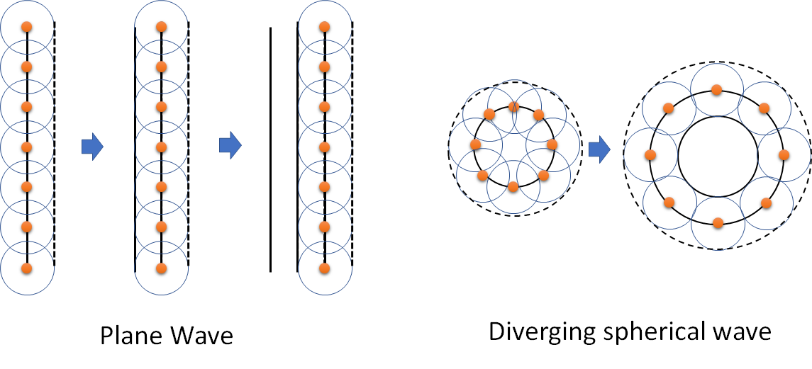
We will talk about the wavefront of a wave. A wavefront is a surface of constant phase. The shape of the wavefront can tell us how the light is propagating. For example, a planar wavefront describes a collimated beam of light. A spherical wavefront describes light which is converging from - or diverging to - a point.
If we have a point source, then the wavefront at a time \(t\) is at a distance \(r\) from the point, where \(r(t) = c t\). Here, \(c\) is the speed of light (for whatever medium the wave is propagating in - more on that later).
Huygens’ principle provides a simple rule to predict the propagation of a wavefront of light. It is empirical, in the sense that is was derived by observations rather than than from any fundamental considerations.
Huygens’ Principle states that each point on a wavefront acts as source of secondary wavelets. These wavelets have the same velocity and frequency as the original wave. The envelope of these wavelets forms the new wavefront.
This says that if we have a wavefront, we can calculate how the wavefront at some future point in time will look by assuming that each point on the wavefront acts as a source of spherical waves. We then take the envelope of these new waves, and that is now the new wave.

Non-examinable Aside: Christiaan Huygens had no explanation of why this seemed to be true. In fact the reason can only be understood in terms of a travelling wave solution to Maxwell’s equations, and in particular the approximate description of this given by scalar diffraction theory, which you will be introduced to later in your studies.
The flaw with Huygens’ principle is that it also suggests that there is a wave running backwards, i.e. there is nothing to encode the direction of the wave. This problem was later solved by Kirchhoff, but that is beyond the scope of this course. Suffice it to say that destructive interference results in the ‘backwards’ wave having zero intensity.
The velocity of light depends on the medium it is travelling through. It can never exceed the speed of light in a vacuum, \(c\), that is to say it propagates more slowly in other materials. The refractive index, \(n\), of that medium determines the velocity.
The refractive index, \(n\), of a medium is the inverse of the ratio of the speed of light in that medium, \(v\), to the speed of light in a vacuum, \(c\): \[n=c/v\]
By definition, the refractive index of a vacuum is 1. Air is about 1.003, which we often take to be 1 for practical purposes. Water has a refractive index of around 1.4, and glass varies from 1.4 (lighter glasses) to 1.7 (heavier glasses).
For most materials, \(n\) decreases (typically by 1-2%) with wavelength over the visible region and beyond into infrared. This gives rise to an effect known as dispersion. Since different wavelengths of light will travel at different speeds in the material, a short pulse of multi-wavelength light will become spread out. This is the ultimate limit on how much data can be sent over fibre optics. It also explains how a spectrum is produced from a prism (see Section [snell]).
Light is a transverse wave, the electric field (and the magnetic field) is perpendicular to the direction of propagation of the light. In linearly polarised light, the E-field points negative or positive along a single direction. In circularly polarised light, the direction of the electric field rotates as the light propagates. In elliptically polarised light the amplitude of the wave varies as the direction rotates. Unpolarised light is made of up of fields pointing in all directions.
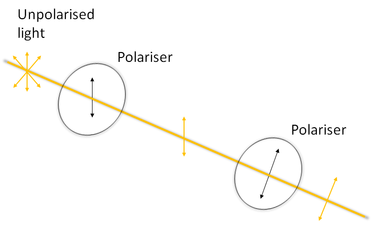
Unpolarised light can be linearly polarised using a polariser such as polarising film. The film has a transmission axis, which is the orientation of polarisaton of light which will be transmitted. If the incident light is unpolarised then the transmitted light will be polarised in the same direction as the transmission axis. If the incident light is polarised then the fraction of light which will be transmitted is given by:
\[\frac{I_{transmitted}}{I_{incident}} = \cos^2 \theta\] where \(\theta\) is the angle between the incident polarisation direction and the transmission axis. If two polarisers are placed at 90 degrees to each other, known as ‘crossed polarisers’ then the transmitted intensity is zero.
